GD&T Basics defines the profile of a line this way:
Profile of a line describes a tolerance zone around any line in any feature, usually of a curved shape. Profile of a line is a 2-Dimensional tolerance range that can be applied to any linear tolerance. If it is called out on a surface, like a radius on a part – profile of a line would specify how much that cross-section could vary from a true curved radius. Profile of a line takes a cross section at any point along the surface and sets a tolerance zone on either side of the profile. The profile of a line callout can also be set with an all-around leader or given a specific range (see example).
GD&T Basics (https://www.gdandtbasics.com/profile-of-a-line/)
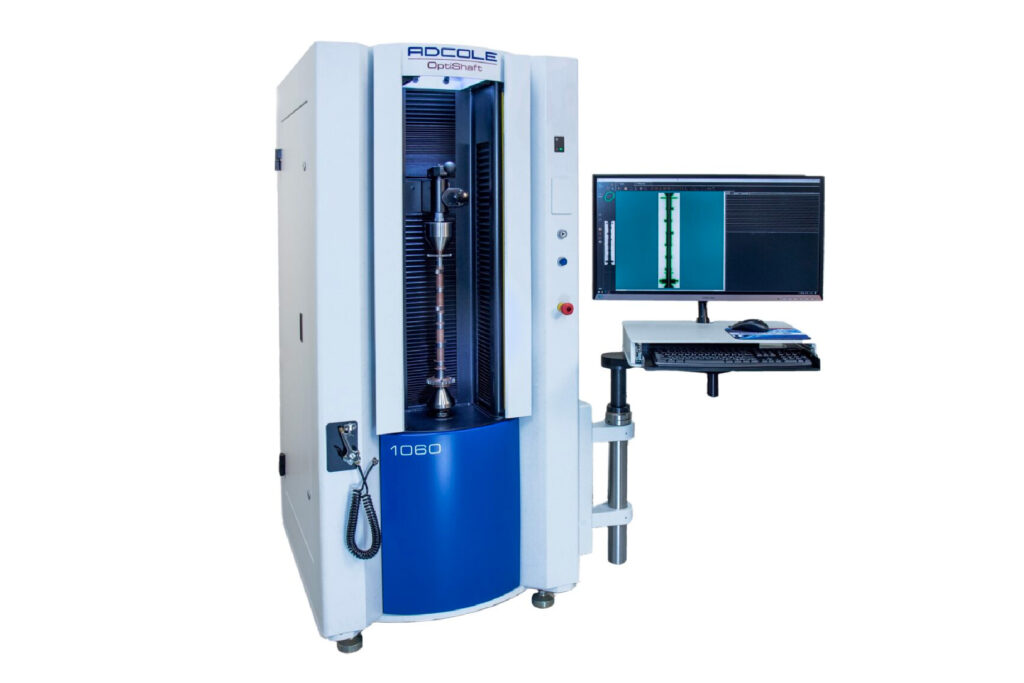
Adcole understands how important linear profile measurements are for advanced manufacturers producing precision components. That’s why Adcole offers Linear Profile Measurement Software — a utility that enables engineers to obtain linear convexity, linear concavity and linear barreling measurements in an easily understood format.
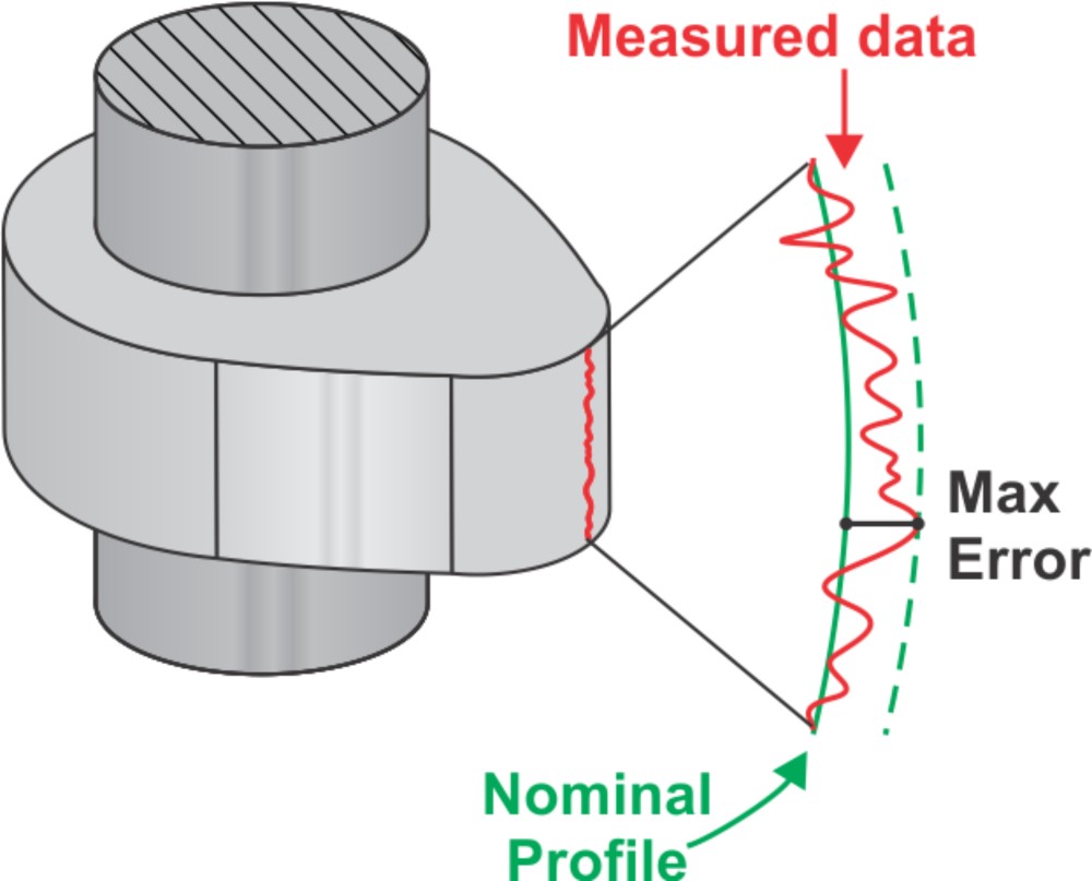
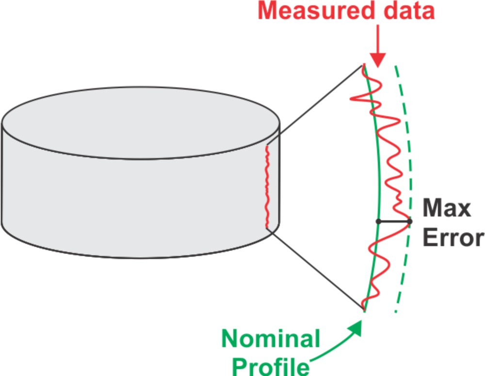
Adcole’s Linear Profile Measurement software provides the ability to compare a linear scan of a journal or a lobe to a known radius. This radius is specified based on nominal information. The output is the largest positive error, largest negative error, and peak-to-valley error. The software allows for plotting of measured profile to nominal profile with tolerance bands, and profile error with tolerance bands.
Linear Convexity & Concavity
The linear convexity measurement is based on determining the maximum positive value of the linear scan data relative to a straight line which has been drawn through the end points of the linear scan. If the linear data that is being analyzed for straightness is not using the data from the full scan, then the straight line is drawn through the end points of the data to be analyzed.
The linear concavity measurement is based on determining the minimum value of the linear scan data relative to a straight line drawn through the end points of the linear scan. If the linear data that is being analyzed for straightness is not using the data from the full scan, then the straight line is drawn through the end points of the data to be analyzed. The result from this value can be a positive or negative value.
Linear Profile
The Linear Profile Measurement software is engineered to map linear profile error relative to a known, or specified profile radius. This capability provides the total profile error, plus the maximum positive and maximum negative data points profile error. The linear profile capability enables users to plot/view both the profile and profile error numerically and graphically. The graphical output shows that the profile is being ground with the proper form and at the intended height axial location –the linear profile is properly aligned. Inthis way, manufacturers can prove that theirgrinding processes are correct and on-spec.
Linear Barreling
The linear barreling measurement is based on determining the value of the center point of the linear data relative to a straight line drawn through the end points of the linear scan. If the linear data that is being analyzed for straightness is not using the data from the full scan, then the straight line is drawn through the end points of the data to be analyzed.
The result from this value can be a positive or negative value. Linear barreling is different from linear convexity in that it only compares the value of the center of the linear scan to the line through the end points.
Features and Benefits
The Linear Profile Measurement Software solution delivers both linear convexity and linear concavity measurements in an easily understood format. The utility offers powerful insights about the granular measurement details of high value, hard to manufacture components. In addition, the software provides linear profile information in numeric and graphical outputs. Lastly, the tool imparts a complete set of data and analysis so that engineers can perform root cause analysis and optimize their organizations manufacturing process.
Manufacturers add the Linear Profile Measurement Software because of the powerful features it offers manufacturers. These include the abilty to compare a linear scan of a journal or a lobe to a known radius. The utility provides output data, including plotted of measured profile to nominal profile with tolerance bands, and profile error with tolerance bands. The solution specifies the radius of high value components based on nominal information. Furthermore, the Linear Profile Measurement Software are able to obtain an accurate comparison of measured data to nominal linear radius, even over an extremely small segment.
To learn more about Linear Profile Measurement Software, check the solution out here.


